
Whether you’re a homeowner planning a renovation, a student entering design school, or a builder coordinating trades, understanding house drawings is essential. Architectural drawings communicate intent clearly and unambiguously so that everyone—from planning officials to site crews—can build the same vision. This guide breaks down the core drawing types, how to read them, and the common pitfalls to avoid.
Architectural Drawing of a House
An architectural drawing of a house is a scaled, technical representation that describes how a home is planned, built, and finished. A typical set includes plans, elevations, sections, and detail sheets that specify dimensions, materials, and construction methods for permitting, pricing, and site execution. Good drawings reduce risk: they align the design team, inform accurate bids, and help avoid costly change orders during construction.
Types of House Architectural Drawings
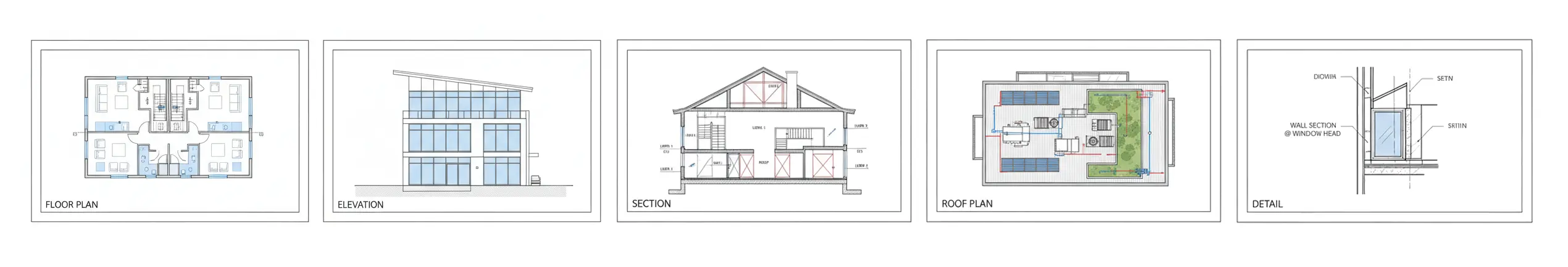
A complete house architecture drawing set is organized so that each sheet focuses on a distinct aspect of the building. Here are the types you’ll see most often and what each contributes.
Floor Plan (the architecture drawing plan)
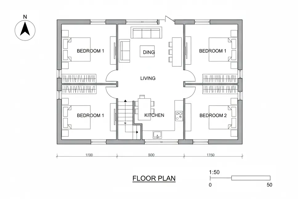
A floor plan shows the home from above at a standard “cut height” (usually ~1.2 m / 4 ft). You’ll read walls, doors, windows, stairs, cabinetry, plumbing fixtures, appliance locations, and critical dimensions. Good plans clarify room sizes and circulation, and they serve as the coordination base for structural, electrical, and mechanical overlays. Look for:
- Overall dimensions (exterior) and interior room dimensions
- Door swings and window types
- Notes for finishes, casework, and built-ins
Site Plan
The site plan situates the house on the lot, showing boundaries, setbacks, orientation, contours/grades, driveway locations, utilities, and drainage. It’s crucial for zoning compliance, grading and drainage design, and situating solar exposure and privacy.
Exterior Elevations

Elevations depict each façade in true scale—heights, openings, materials, and key levels (e.g., finished floor, sill, head, and ridge). You’ll see cladding types, trim profiles, roof pitches, and exterior fixtures. Elevations help finalize the look and guide pricing for materials and labor.
Building Sections
A section is a vertical “slice” through the building, revealing floor-to-floor heights, stair rises/runs, foundation and roof assemblies, and insulation strategies. Sections are indispensable for constructability and for catching conflicts between structure and services.
Roof Plan
The roof plan shows slopes, ridges, valleys, hips, eaves, gutters, downspouts, and penetrations (vents, skylights). Correct roof geometry and drainage notes prevent leaks and ice dams, and they coordinate with structural framing.
Reflected Ceiling Plan (RCP)
An RCP shows the ceiling as if reflected onto the floor: soffits, bulkheads, beams, lighting layouts, sprinkler heads, diffusers, and access panels. Use it to coordinate electrical and HVAC with cabinetry and structural elements.
Electrical & Low-Voltage Plans
These drawings locate outlets, switches, circuits, panels, data points, speakers, and smart-home devices. They include switching logic (e.g., 3-way switching at stair landings) and circuiting notes for load balancing.
Plumbing & Mechanical (MEP) Plans
Plumbing diagrams show fixture connections, pipe sizes, vents, cleanouts, and water heater locations. Mechanical plans outline equipment, duct runs, registers/returns, and ventilation strategies. Good MEP sheets prevent clashes and reduce rework during rough-in.
Details & Schedules
Details zoom in on assemblies (window heads/sills, wall/floor junctions, waterproofing, flashing, stairs, railing, and insulation). Schedules (doors, windows, finishes, lighting) consolidate specifications in an easy-to-reference format. Details and schedules are where many cost and durability decisions are made.
This guide explains the most common drawings of a house architectural set and how to read them without confusion.
How to Read Drawings of a House (Architectural)
Even a well-drafted set can be intimidating at first glance. Use the checklist below to build confidence and speed.
1) Start with the title block
The title block (usually along the right or bottom margin) identifies the project, sheet number, drawing title, scale, designer/architect, dates, and revision history. Confirm you’re viewing the latest issue: revision clouds or delta symbols mark changes since the previous set.
2) Understand scale and units
Residential drawings commonly use 1:50 (metric) or 1/4″ = 1′-0″ (imperial) for plans and elevations. Details jump to larger scales (1:5–1:20 metric; 1 1/2″ = 1′-0″ and up in imperial) so you can see construction layers. Keep a scale ruler—or a PDF viewer with measurement tools—handy.
3) Learn the line types and hatches
- Cut elements (walls cut through) are drawn heavier than items seen beyond.
- Hidden lines (dashed) indicate overhead features (e.g., beams or cabinets).
- Centerlines mark symmetry axes or fixture centers.
- Hatching denotes materials (e.g., concrete, insulation, sheathing).
The legend or general notes often define the graphic conventions used across the set.
4) Follow dimensions and datums

Plans dimension to centerlines or faces of framing; elevations and sections dimension vertically from a datum (often finished floor). Read dimension strings from outermost (overall) to innermost (rooms or components). Pay attention to tolerances and “verify on site” notes.
5) Cross-reference markers
Callouts like “A-301/2” mean: drawing 2 on sheet A-301. Section, elevation, and detail markers connect the set; use them to move from a plan to the corresponding section or detail. This is how you build the 3D picture in your head.
6) Watch for notes, tags, and schedules
Keynotes and tags (e.g., D-12 for a door type) reference schedules where sizes, materials, fire ratings, glazing, and hardware are specified. Always reconcile what you see in plan with the schedule—bid errors often come from skipping this step.
7) Verify clearances and codes
Read door swing clearances, stair headroom, egress widths, window egress requirements, and bathroom fixture clearances. Local code notes may appear in general sheets or within specific details; when in doubt, confirm with the designer.
Common Mistakes & How to Avoid Them

- Using outdated revisions
Always check the revision index and issue date before printing or building. Maintain a controlled drawing set on site. - Ignoring scale and real dimensions
Never “scale off” a printed drawing unless explicitly allowed. Use dimension strings and ask for clarifications when missing. - Uncoordinated overlays
Verify that structural framing aligns with openings and that MEP routes avoid beams and joists. Clash detection—even manually—saves time on site. - Ambiguous notes and abbreviations
If a note is unclear, request a written clarification (RFI). Don’t allow trades to interpret differently. - Incomplete details
Critical assemblies (window flashing, roof-to-wall junctions, slab insulation) need clear details. If missing, ask for additional sheets before construction. - Wrong orientation
Confirm the north arrow and “front” definition. Orientation affects solar control, privacy, and openings strategy.
Quick Reference Table
Drawing | What it shows | Why it matters | Typical scale |
Floor plan (architecture drawing plan) | Rooms, walls, doors, windows, fixtures | Layout, circulation, furniture | 1:50 (metric) or 1/4″ = 1′-0″ |
Site plan | Lot boundaries, setbacks, grades, utilities | Zoning, siting, drainage | 1:200–1:500 |
Exterior elevations | Façades, heights, materials | Design intent, openings, finishes | 1:100 or 1/8″ = 1′-0″ |
Building sections | Vertical cuts, assemblies | Constructability, conflicts, heights | 1:50–1:100 |
Roof plan | Slopes, ridges/valleys, drainage | Waterproofing, coordination | 1:100 |
Reflected ceiling plan | Ceilings, soffits, lighting | Electrical/HVAC coordination | 1:50–1:100 |
Electrical/Low-voltage | Outlets, switches, circuits, data | Functionality, load, smart-home | Match plan scale |
Plumbing/Mechanical | Fixtures, supply/vent, ducts | Performance, serviceability | Match plan/section scales |
Details & schedules | Assemblies; door/window/finish lists | Buildability, takeoffs, specs | 1:5–1:20 (details) |
Tools and File Coordination (Optional but Helpful)
Even if you’re reviewing PDFs, it helps to know where these drawings originate:
- CAD/BIM suites produce coordinated plans, elevations, and schedules; changes update across sheets.
- 3D modeling tools support massing and visualization for design reviews.
If you’re choosing software for design visualization or coordination, see our studio-tested guide:
Best 3D Modeling Software for Architecture in 2025: Studio-Tested.
Downloads & Next Steps
- Checklist: Before issuing a drawing set, verify scale, sheet index, revision log, dimension completeness, door/window schedules, and code notes.
- On-site binder: Keep a printed, date-stamped set in a weatherproof sleeve and require crews to mark revisions immediately.
- Change control: Establish a single source of truth (cloud folder or document control system) and communicate updates to all trades.
If you’re a homeowner or developer, ask your architect for:
- a one-page legend of symbols and abbreviations used in your set, and
- a sheet index annotated with what each drawing covers.
These two documents alone can reduce back-and-forth by half.
The Bottom Line
A clear, coordinated drawing set is the backbone of any residential project. Learn the sheet types, read the title block and scales first, follow cross-references, and double-check schedules. With those habits, you’ll navigate drawings confidently, make faster decisions, and build with fewer surprises. And when you need to visualize options or coordinate complex geometry, pair your drawings with the right modeling tools—your schedule and budget will thank you.